8 June 2026
The motivation behind this write up was born from my desire to verify
that the system clock settings were proper. This involved the initial,
somewhat naive approach of checking the SystemClockConfig
global variable since when writing application code it is used to track
the clock configuration. Along the way, however, I was reminded that
during startup any non-constand (read-only) data is stored in the
.data section, which requires some time to be loaded into
RAM. This amount of time is small, but existant, and caused me some
brief confusion as to why it would report different values than what I
expected.
At the end of the day, a global variable is still just a variable and requires proper initialization and strict updating procedures for it to be useful in any way. Global variables are ultimately reliant on the careful analysis of the initial and reset register conditions along with carefully writing to and monitoring various registers. Outside of the registers, the only thing giving value to the global variables is the attention to detail in the application code handling them.
In addition to that, it provided an opportunity to learn that there are multiple types of resets. Most people think of the simple cases of power cycling, or maybe pressing the reset button, but depending on the type of reset, some registers may or may not be reset. This is critical to understand if you want to truly understand all cases possible.
With that said, the following is more a log of my notes while checking the clock, and perhaps you may find something useful in it, or at least remember to appreciate all of the work that is done behind the scenes when not writing every detail of the startup yourself.
The journey began by connecting a JLink and Nucleo board to my computer, and then connecting the JLink to the Nucleo board for SWD interaction. For details on how this was done please refer to this page.
Connections were verified, and JLinkGDBServer was initialized, which listens on port 2331.
prompt$ JLinkGDBServer -device STM32C031C6 -if SWD -speed 4000In a separate terminal, arm’s provided version of GDB was invoked and attached to the JLinkGDBServer.
prompt$ arm-none-eabi-gdb /path/to/executable.elf
(gdb)target remote localhost:2331
After connecting we’ll want to reset though. Running the following lets us do that
monitor halt
load
monitor reset
you can also use monitor reset 0, but both work, as 0 is
the default, and it means it will reset and halt so that no code
executes. There are different types of reset strategies according to
SEGGER.
However, this peaked my interest - what types of resets are there and what do they do? I initially thought all resets were treated equally.
Checking the C031C6’s datasheet (RM0490) we find multiple resets described on page 118, s6.1.1.
Similarly, if we check SEGGER’s documentation on reset strategies we see there are several types for Cortex-M devices.
Now, we could spend a whole day on the details of each, but let’s focus on the common/expected ones - using SEGGER’s default, power reset, and reset pin.
SEGGER’s Type 0, the default, aims to be a general strategy since it attempts to be device-specific and tries to ensure proper actions are taken depending on the target. Segger outlines here the C031C6 uses no special handling, and follows the default rules:
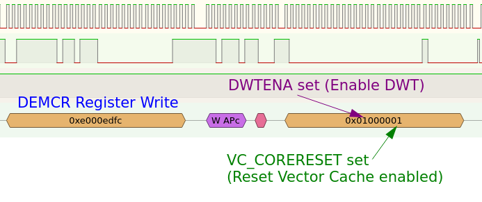
- Setting VC_CORERESET in DEMCR (halt after reset)
- Set SYSRESETREQ in AIRCR (reset core and peripherals)
- S_RESET_ST in DHCSR goes high (reset active) then low afterwards
- VC_CRERESET cleared
[!NOTE] Go back and add all this to a separate write up, keep it brief here.
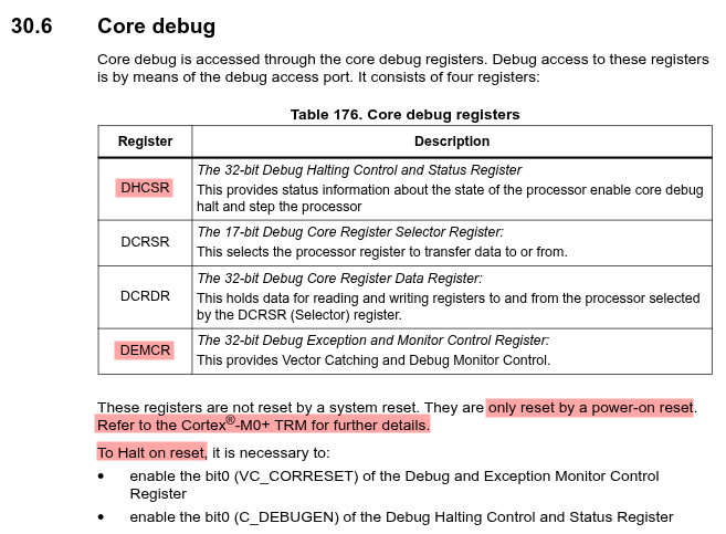
ABOVE: RM0490 Core Debug Register Overview (DEMCR and DHCSR included)

ABOVE: PM0223 AIRCR general description
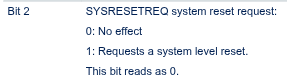
ABOVE: PM0223 AIRCR bit2 description
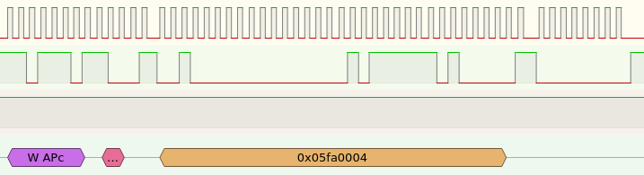
ABOVE: Using VECTKEY = 0x05FA allows writing and
0x0004 sets SYSRESETREQ
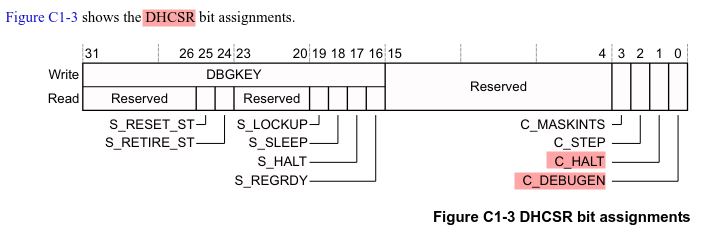
ABOVE: ARMv6M-ARM DHCSR Bit Assignments
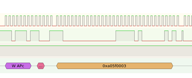
ABOVE: Using DBGKEY = 0xA05F allows writing and
0x0003 sets C_HALT and
C_DEBUGEN.
DEMCR
- Described in page 1007 RM0490
- Accessed through core debug registers
- Provides Vector Catching and Debug Monitor Control
- Reset by power-on reset, not system reset
- Enable bit 0 of DEMCR to halt on reset
  (along with bit0 of DHCSR)

AIRCR
- Describe in pages 59,60 of PM0223
- Described in page 1007 RM0490
- Part of System Control Block registers
- Have to write 0x05FAXXXX to write
- Writes 0x05FA0004 to set bit2 (SYSRESETREQ)
  to request system level reset

DHCSR
- Described in page 1007 RM0490
- Accessed through core debug registers
- Provides status informationabout state of the processor
- Provides info on enable core debug halt and step the processor
- Must enable bit0 (C_DEBUGEN) to halt on reset
  (along with DEMCR bit0)
o
After this let’s check our clock.
(gdb) monitor reset 0
Resetting target (0 = NORMAL: Resets core & peripherals via SYSRESETREQ & VECTRESET bit.)
(gdb) print SystemCoreClock
$1 = 48000000
(gdb) print &SystemCoreClock
$2 = (uint32_t *) 0x20000000 <SystemCoreClock>
That’s odd, since the clock should be at 12MHz, not 48MHz. However,
remember that SystemCoreClock is a global variable and not a
register in the chip and it appears to live at the start of RAM.
Regardless of where it lives, it is in RAM. You might think it should
have the proper start value, since in system_stm32c0xx.h on
line 116 we see
uint32_t SystemCoreClock = 12000000UL;It seems odd, until you remember when we halt, we haven’t allowed the chip to actually do any setup, which involves copying the data section into memory, and so the RAM will contain a garbage value, or the value from the previous run before being halted. We can actually demonstrate this two ways. First, let’s write a quick function to let us see when it is loaded into memory.
define infostep
i r pc
si
print SystemCoreClock
end
This will print the program counter contents, execute the command, and show the value of the variable, so we can find out when it changes.
(gdb)
72    bcc CopyDataInit
$16 = 48000000
(gdb)
pc             0x8000b50           0x8000b50 <Reset_Handler+28>
62    ldr r3, =_sidata
$17 = 48000000
(gdb)
pc             0x8000b40           0x8000b40 <Reset_Handler+12>
63    ldr r3, [r3, r1]
$18 = 48000000
(gdb)
pc             0x8000b42           0x8000b42 <Reset_Handler+14>
64    str r3, [r0, r1]
$19 = 48000000
(gdb)
pc             0x8000b44           0x8000b44 <Reset_Handler+16>
65    adds r1, r1, #4
$20 = 12000000
And we see that it is properly initialized during the Reset_Handler routine during the copying of data.
If we were to reset now and check again, we’d see the variable save this value since it reuses the same RAM address:
(gdb) monitor reset
Resetting target
(gdb) print SystemCoreClock
$22 = 12000000
(gdb) print &SystemCoreClock
$23 = (uint32_t *) 0x20000000 <SystemCoreClock>
(gdb) i r pc
pc             0x8000b48           0x8000b48 <Reset_Handler+20>
And just to prove this, let’s set it to something silly. First, let’s let the program run and see that the variable changes to 48MHz, then we’ll change it.
(gdb) monitor go
(gdb) monitor halt
(gdb) print SystemCoreClock
$24 = 48000000
(gdb) monitor memU32 0x20000000=0xDEADBEEF
Writing 0xDEADBEEF @ address 0x20000000
(gdb) print SystemCoreClock
$25 = 3735928559
(gdb) x/x &SystemCoreClock
0x20000000 <SystemCoreClock>:   0xdeadbeef
(gdb) monitor reset
Resetting target
(gdb) x/x &SystemCoreClock
0x20000000 <SystemCoreClock>:   0xdeadbeef
And we see that it does in fact hold over. But this begs the question, how do we check the clock then? Registers.
We’ll note from the datasheet RM0490 that the RCC’s base is (from
Table 7) 0x4002 1000. And some important registers are
We’ll want to ensure they start at their reset values, since the SystemCoreClock is assigned based on what should be expected during a restart. From RM0490 again we note they should be as follows:
RCC_CR  (offset 0x0) ---> 0x0000 1540 (Page 136)
RCC_CFG (offset 0x8) ---> 0x0000 0000 (Page 133)
Looking at the individual bits for each register we find the following settings should be what startup indicates.
Splitting it into two byte groups for easier readability, R indicates reserved. We’ll go from Hex -> Binary with spaces -> Remove spaces and then finally we’ll group the bits according to specific register values and give them letters for examination. This will simply make it easier to read.
First bytes 0x0000
Hex:  0x0000
Bits: 0b000 000 000 000 0000
      0b0000000000000000
      0b00000000 0 0 00 0 0 0 0
      0bRRRRRRRR a b RR c d e f

(a) 0 --> HSIUSB48RDY = Not applicable for C031
(b) 0 --> HSIUSB48ON  = Not applicable for C031
(c) 0 --> CSSON       = Disable (Disabled clock security system)
(d) 0 --> HSEBYP      = No Bypass (Internal HSE osc. bypassed to use external)
(e) 0 --> HSERDY      = Not Ready (HSE Oscillator not stable/ready for use)
(f) 0 --> HSEON       = Disble (Cleared when entering stop, standby, shutdown)
Last bytes 0x1540
Hex:  0x1540
Bits: 0b0001 0101 0100 0000
      0b0001010101000000
      0b00 010 1 0 1 010 000 00
      0bRR  a  b c d  e   f  RR

(a) 010 --> HSIDIV    = 4 (HSI48 clock divider for HSISYS clock)
(b)   1 --> HSIRDY    = Ready (HSI48 enabled through HSION and stable)
(c)   0 --> HSIKERON  = HSI48 Active in Run and Stop modes
(d)   1 --> HSION     = Enable (High when system clocked derived from HSI48)
(e) 010 --> HSIKERDIV = 3 (division for kernel clock)
(f) 000 --> SYSDIV    = 1 (no division for system clock)
We see the HSIDIV and HSION are what is responsible for the expected 12MHz initial system clock, not 48MHz, along with the HSE bypass being off for the moment.
We’ll do the same except it’s just all 0’s this time so we’ll keep it in one group an label again with R for reserved and letters for groups corresponding to important values in the register.
Hex:  0x00000000
Bits: 0b0000 0000 0000 0000
      0b0000000000000000
      0b0000 0000 0000 0000 0 000 0000 00 000 000
      0b  a    b    c    d  R  e    f  RR  g   h

(a) 0000 --> MCOPRE  = 1 (Division factor of clock sent to MCO output)
(b) 0000 --> MCOSEL  = no clock (Sets clock selector for MCO Output)
(c) 0000 --> MCO2PRE = 1 (Division factor of clock sent to MCO2 output)
(d) 0000 --> MCO2SEL = no clock (Sets clock selector for MCO2 output)
(e)  000 --> PPRE    = 1 (Division factor of HCLK to produce PCLK)
(f) 0000 --> HPRE    = 1 (Division factor of SYSCLK to produce HCLK)
(g)  000 --> SWS     = HSISYS (Hardware controlled indicator of system clock)
(h)  000 --> SW      = HSISYS (Selects clock for SYSCLK)
So we see that HSISYS is selected as SYSCLK with no division factors, and since the RCC_CR registers configured HSI to be divided by 4, it means we’re using 12MHz all around.
Good, now lets check to make sure these are the values
So, picking up where we left off, we can see that these setting are correct even when working with a garbage leftover value for SystemCoreClock.
(gdb) monitor reset
Resetting target
(gdb) x/x &SystemCoreClock
0x20000000 <SystemCoreClock>:   0xdeadbeef
(gdb) x/x 0x40021000
0x40021000: 0x00001540
(gdb) x/x 0x40021008
0x40021008: 0x00000000
(gdb) monitor go
(gdb) monitor halt
(gdb) x/x 0x40021000
0x40021000: 0x00031540
(gdb) x/x 0x40021008
0x40021008: 0x00000009
(gdb) x/x &SystemCoreClock
0x20000000 <SystemCoreClock>:   0x02dc6c00
(gdb) p SystemCoreClock
$26 = 48000000
And notice we let it run (the monitor go command) and we
see the global variable did indeed update eventually, and the RCC
registers did as well.
They changed slightly, we’ll note only the changes below
The 0x0000 1540 --> 0x0003 1540 change affected the
first bytes 0x0000 and changed the values for e and f for the RCC_CR
register as noted below.
0b00000000 0 0 00 0 0 1 1
0bRRRRRRRR a b RR c d e f

(a) Unchanged.
(b) Unchanged.
(c) Unchanged.
(d) Unchanged.
(e) 1 --> HSERDY      = Ready (HSE Oscillator is stable/ready for use)
(f) 1 --> HSEON       = Enable (Can't be cleared when HSE is used for SYSCLK)
So we see eventually the HSE is enabled and is stable and ready for use.
The 0x0000 0000 --> 0x0000 0009 change affected the
last byte and changed the values for g and h in RCC_CFG as noted
below
0b0000 0000 0000 0000 0 000 0000 00 001 001
0b  a    b    c    d  R  e    f  RR  g   h

(a) Unchanged.
(b) Unchanged.
(c) Unchanged.
(d) Unchanged.
(e) Unchanged.
(f) Unchanged.
(g)  001 --> SWS     = HSE (Hardware controlled indicator of system clock)
(h)  001 --> SW      = HSE (Selects clock for SYSCLK)
We see the HSE was eventually selected to be used as the system clock. Note that the divide by 4 earlier was for HSI not HSE, and all dividers are 1 still, so it means we are in fact using the HSE clock at full speed, 48MHz, which does match what the SystemCoreClock variable was eventually set to after allowing the program to run.
We verified that initially the clock settings are valid, and line up with the expected reset value of 12MHz using the HSI clock, and that the global variable SystemCoreClock can’t be trusted for the very first few instructions until it’s value is loaded from flash into RAM. Then we showed that given enough time, the HSE is configured and the SystemCoreClock variable is updated as well.